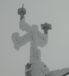
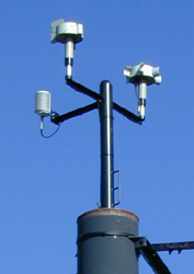
 Sensors are the visible part of a weather station. They must be exposed to
the weather so that they may take measurements.
Sensors are the visible part of a weather station. They must be exposed to
the weather so that they may take measurements.
Wind Speed
Purpose: To measure how quickly the air mass of a weather system is moving.When weather systems move past a location the movement of the air is described as wind. The higher the wind speed, the quicker a weather system will be replaced with the next.
Wind can affect the environment in obvious ways, stressing rigid structures (like trees and buildings), and moving portable items (like new snow or your picnic lunch). It contributes to other subtle effects, such as windchill, which is a measure of how quickly heat is lost from a warm body.
Winds can have delayed effects as well. New snow, blown over ridge-tops by the wind, can form avalanche-triggering cornices. This hazard may release during a storm, or remain and continue building throughout a winter.
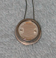
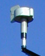
General details: The sensor uses a hub with six paddles on its side which spins on a vertical axis. A magnet is attached to the hub, and a "Hall effect" sensor detects the magnet's movement as the hub revolves. The sensor provides one pulse per revolution.
Protection against icing is provided by an internal 1100 Watt heater and a temperature sensor connected to a thermostat. The sensor is kept at about 35 degrees (F) to avoid freezing. Its construction is heavy gauge aluminum.
Specific details: Made by Hydro-Tech (Seattle, Washington), heated rotor anemometer Model WS-3. The business name was "Taylor Scientific Engineering" in summer of 2001.
The Hall effect sensor is a three terminal device, powered between +12 volts and ground, with an NPN open-collector output. It's output is a nominally 50% duty cycle square wave.
The +12 volt power is jumpered from the temperature/humidity sensor's supply at the base of the tower. Ground and the output run on a single pair of wires to the datalogger.
Hall sensor       Cable (tower)     Cable (12-pair)      Datalogger

  +12V power      .                 x
  Output          .                 Blu/Wht ->(Buffer)-> "P1" - Pulse counter
  Ground          .                 Wht/Blu              "G"  - Ground (digital?)
The datalogger's "P1" pulse input should not be driven with signals which swing over +5.0 volts, so a signal level conditioning circuit is used to reduce the swing:
The Hall-effect sensor's output is buffered using a "NE555" chip (near the datalogger), to allow level shifting to a 0-5 volt swing. The same buffer output provides the line drive to send this signal to the bottom of the hill.
The downhill wire pair is "Wht/Grn" at the terminal block in the radio cabinet. It is connected to the Yellow/Orange wire pair in the large cable going to the lodge. This wire pair is about one mile in length, each leg has about 37 Ohms of resistance (73 Ohm shorted loop), in excess of 20 MegOhm leakage to ground (or other wires). Its capacitance is unknown.
Maintenance: The manufacturer's manual calls for an annual check of the bearings for noise and starting torque. Any noise from the bearing will be associated with increased friction, which will affect the sensor's calibration.
The starting torque (required to get the rotor to start spinning) can be measured with a "torque watch". (This is a very sensitive instrument, the torque is very small.)
Consider lubrication or replacement of the bearings as a result of this check.
Another way of detecting bad bearings: When readings start dropping to "0" in light wind conditions. It seems that the wind is rarely calm for long on top of a mountain.
The deicing heater controller should be turned-on and set to around "65" on its 0..100 scale for winter-time operation (Nov 15 to Apr ?). Set to about "50" for one month prior to and after "Winter". Turn-off the heater during warm weather months.
Calibration: The physical structure of the wind rotor essentially defines how it responds to wind speed. As long as the rotor is not deformed and it spins freely on its axis, there should be no concerns about its calibration.
The rotor has a nominally linear response of revolution rate (RPM) to wind speed (MPH). At 100 MPH it should spin at 850 RPM and generate 850 pulses per minute. Due to starting friction the minimum measureable wind speed is around three (3) MPH.
Comments:
None.
Air masses coming from different directions often have different
characteristics, so a change in wind direction often "announces" the arrival of
a new weather system.
In case of high winds, the direction from which it comes can dramatically
affect what sort of dangers those winds may create, and where those hazards are
located.
Mountains tend to block winds, so conditions are calmer off the top of the
mountain and on the leeward side (away from the wind).
General details:
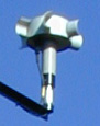
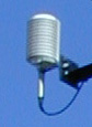
The sensor uses a simple weather vane (a hub with a
tail) mounted on a vertical axis. Directions are sensed with a 5000 Ohm linear
potentiometer attached to the vane. The electrical resistance between the
potentiometer's wiper and one of its ends varies with its rotation. The zero (0)
Ohms direction is usually aligned with "North", and resistance increases
proportional to compass bearings (0..360).
Protection against icing is provided by an internal 1100 Watt heater and a
temperature sensor connected to a thermostat. The sensor is kept at about 35
degrees (F) to avoid freezing. Its construction is heavy gauge aluminum.
Specific details: Made by Hydro-Tech (Seattle, Washington), heated
direction vane Model WD-3. The business name was "Taylor Scientific Engineering"
in summer of 2001.
Sensor connections are the three potentiometer terminals.
Jumpers at the base of the tower connect the 3 wires coming from the
potentiometer to 3 pairs of wires going to the datalogger. This allows "4-wire"
resistance measurements to be made at the tower's junction box.
To make a measurement a 1.0 Volt signal is applied to the ends of the
potentiometer using one of the wire pairs. A second wire pair allows a
differential voltage measurement from the wiper to common. The third wire pair
allows a differential measurement across the whole potentiometer (high-end to
common). The ratio of the two measurements is computed and scaled to provide an
output with values ranging 0-to-360 (degrees) for the compass direction.
Maintenance:
The manufacturer's manual calls for an annual check of
the bearings for noise (& starting torque (??)); lubricate or replace the
bearings or potentiometer as necessary (??).
Calibration:
As long as the potentiometer is not damaged or worn, its
linearity should remain adequate for the task. Since the measurement
computes a ratio of voltages, the absolute value of the potentiometer's
resistance is not critical.
The potentiometer's resistance is expected to be proportional to the compass
bearing, so its resistance should go from minimum to maximum in the direction of
true North. The physical orientation of the sensor should be verified
if there is any reason to suspect that the mechanical set-up has turned.
As mounted on top of Hoodoo Butte, "North" is in the direction of the bottom
of the ravine containing Hoodoo Creek, just west of Hogg Rock. (Midway between a
left tangent to the highway around Hogg Rock and the rock outcrop at the east
end of Potato Hill, about 1000' west of the highway. As a secondary check, the
lift cable's axis runs almost exactly NE/SW.
Comments: None.
Humidity is a measure of how much water vapor is in the air, as compared to
the maximum possible amount. It is expressed as a percentage.
Humidity usually doesn't affect much until it gets close to 100%, at which
point the vapor turns to liquid and we get fog, clouds, or precipitation.
If we monitor the humidity we can estimate how close we are to losing
visibility. At "saturation", as the temperature drops, fog will form. As the
temperature goes below freezing, rime can form as supercooled (still liquid)
water droplets freeze on contact with cool objects like towers, trees and
skiers. As the temperature continues to drop the droplets freeze into ice
crystals, and we get snow.
In the summer, low humidity is very important when considering forest fire
danger.
General details:
This sensor is combined with the temperature sensor
in a single package. It uses a material which changes its electrical resistance
in response to how much moisture it has absorbed from air.
Specific details: See the "Temperature" sensor's section, since the
sensors are combined.
An internal "drive" circuit applies a stimulus (e.g. current) to the sensor,
and measures a response (e.g. voltage).
Maintenance: See the "Temperature" sensor's section.
Calibration: Nothing is actively done. Measurements and visual
observations are often compared, to ensure that a reading of 98% or higher is
associated with the sensors being in fog or heavy precipitation events.
Comments: None.
Since the absolute air pressure varies with both weather and elevation, it is
customary for stations to convert their reading to a sea-level equivalent so
that readings from different stations can be easily compared. For this station,
at 5720', the absolute pressure is 80.2% of "sea-level pressure".
Air pressure and winds are closely related. Dropping pressure can be a
leading indicator of winds to come, as air masses are drawn toward lower
pressures. High pressure tends to hold-out winds, and is often associated with
clear and calm conditions.
General details:
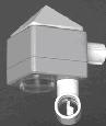
The sensor uses a silicon pressure sensor whose
output is buffered by operational amplifiers. The sensor also contains its own
voltage regulator and internal temperature sensor.
The pressure sensor requires a temperature correction.
Specific details: The sensor is mounted within an aluminum block, with
a pigtail of wires.
Maintenance:
None.
Calibration:
There is no calibration schedule, so this sensor's
readings should be considered to be an "indicator" and not a "gauge". While the
absolute value reported has an unknown error, it is still useful for detecting
trends from the graphical display.
Attempts are occasionally made to develop correction factors by tracking this
sensor's pressure & internal temperature readings, as compared to a weighted
average of pressure readings for the
Corvallis
and Redmond
airports. Redmond is closer, so its reading is given a 2/3 weighting.
Comments:
Design and hardware courtesy of Mike Linse.
The snow pack depth affects how fully rocks & trees may be covered, and
how much skiable terrain may be available. For skiers there can never be enough
snow (well, outside of the roads & parking lot).
By watching short-term variations in snow depth, we can tell roughly how much
new snow has fallen during a storm.
If you have ever made a snowball, you know that snow can be compacted. The
snow pack is continuously "settling" under to its own weight, even if it isn't
melting. Lighter (colder) snows will eventually compress significantly over
time, while heavier (warmer) snows will compress less, but do so more quickly.
General details:
The distance from the sensor to the ground (or snow pack) is computed based
on the echo timing. It is also corrected for temperature, as the speed of sound
in air is a function of temperature. By subtracting the measured distance from
the distance to the ground, we get the snow depth.
Specific details:
Made by
Judd Communications,
it is a reasonably general purpose
depth sensor
which is suitable for sensing a snow surface.
Maintenance:
Inspect the air temperature sensor housing, to make sure it is free of insect nests.
The manufacturer cites the average life of the ultrasonic transducer at about 3-5 years.
After a little over 7 years of operation, as we see degradation in the ability to
take consistent measurements, they suggested it may be time to replace the transducer.
They offer a transducer replacement kit, or the unit can be sent back for servicing and
a full check-out.
Calibration:
A tape measure blade attached to the sensor tower allows mid-season
verification.
The sensor uses a quartz crystal timebase to measure the echo times.
These oscillators tend to be very stable.
Comments:
The sensor measures and applies a correction for temperature, but the air path
is not always uniform. Wind may tend to blow the sound beam around, leading to
longer apparent path lengths.
The sensor is mounted on a wooden (4x6) mast, which might tend to warp due to
changes in humidity and heating from the sun.
The snow depth sensor may also get "fooled" due to an incorrect air temperature reading:
The mid-day sun may heat the sensor more than the air, which results in an incorrect
speed-of-sound correction in the echo distance measurement. If the sensor is warmed
more than the air, and the distance calculation assumes a faster speed-of-sound than
actual, it will compute an echo path length which is greater than what it should be.
Since snow depth is computed as the height of the sensor MINUS the echo path length,
a longer path results in a lower computed snow depth. And that is what we often see
around mid-day and early afternoon on sunny days.
Most measurerment variations are "one sided", to a lower apparent snow depth. We tend
to credit these to wind and temperature causes.
There are times when wildy random values are seen, and these are believed to be related
to power main noise corrupting the ultrasonic echo-ranging. This noise is highly
correlated to the in-area chairlifts operating under heavy load. Their variable
frequency motor drives tend to put a lot of impulse noise onto the power main. If a
false echo is "heard" due to such an impulse, it would be heard before the real echo
would have returned, leading to a shorter range "measurement", and a higher-than-expected
snow depth "reading". And this is what we see when there are "wildy random" noisy
measurements.
Overall, the readings seem to vary plus or minus an inch or less. The "wildly random"
readings often add over one hundred inches.
This sensor was originally installed in the Fall of 2001. It was serviced at least
two times, and was replaced in the Summer of 2020.
There is a lingering difficulty of interference related to night skiing lighting.
As soon as the lights are turned-on it is virtually impossible to get a reading
until the lights are turned-off. Noise on the power main? Ultrasonic sound from
the LED lighting? We haven't been able to determine the mechanism.
And a small problem, probably water freezing and opening a connection in the serial
data lines, where the sensor goes temporarily, but profoundly, dead. These conditions
happen when it starts snowing. Can't troubleshoot this sort of problem when it's warm
or dry, just when the weather has turned nasty. :-(
General details:
The sensor collects precipitation in an antifreeze solution, converting it to
a liquid. The solution is stored in a tall cylinder, where the depth of the
"water" corresponds to the amount of precipitation received.
The hydrostatic pressure at the bottom of the cylinder corresponds to the height
of the water level, so a pressure sensor is used to measure how much water has
been collected.
The cylinder is occasionally drained, so it doesn't overflow. If drained before
the end of the water year, an offset will need to be added to subsequent
measurements, to account for the equivalent amount of precipitation removed from
the cylinder.
Temperature variations affecting the cylinder, the water, and the pressure
sensor contribute to short-term variations in the meaurement. The cylinder
and water may expand or contract in volume at different rates with variations
in temperature, similar to a liquid-in-glass thermometer. Due to thermal
gradients in the structure, these effects are not easily corrected. The
pressure sensor can be temperature compensated for its own part.
Long-term variations can be expected due to evaporation, and of course, the
stuff we are trying to measure.
Like most designs, advantages come with disadvantages: Ordinary "tipping bucket"
rain gauges can easily resolve 0.01", but their mechanism doesn't work well with
frozen precipitation. (Heaters can be used, but they require significant energy
which may not be available at battery or solar-powered sites.) An antifreeze-filled
bucket doesn't suffer if ice or snow falls into it, but resolving small changes
in its depth is difficult.
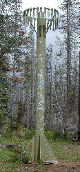
To reduce wind effects, a "calming device" of hanging vanes surrounds the
collection funnel. It helps somewhat to reduce horizontal wind velocity,
but is primarily intended to reduce updrafts. Since the collection funnel
is many feet above ground level, wind currents not present at the ground
might otherwise tend to blow lighter precipitation (e.g. snow) past the sensor.
Specific details:
A web page by
Honeywell
Sensotec was found, which briefly describes the gauge. The pressure
transducer is a Honeywell Sensotec
model TJE.
The antifreeze solution may be a mixture of ethyl alcohol and propylene glycol,
which is used in some snow pillow sensors.
It is not known if a floating cover layer (like an oil) is used to inhibit
evaporation.
Maintenance:
Calibration:
The pressure gauge should provide calibrated measurements of hydrostatic
pressure.
The antifreeze solution's density, possibly varying with the amount
it has been diluted, is important to track.
The local gravitational constant ("g") probably hasn't changed enough
to worry about.
Unless hit by a falling tree or bulldozer, the shape and size of the collection
funnel and cylinder probably do not need to be re-verified. Their physical
sizes result in a volume of fluid being collected, and made measureable as a
depth of water.
Comments:
The
Hogg Pass SNOTEL site
is about two miles northeast of Hoodoo Butte, near Santiam Pass on highway US20.
Historical data, beginning October 1, 1979, is available.
The next closest SNOTEL site is at
Santiam Junction,
about three miles northwest of Hoodoo Butte. It's about 1010 feet lower than the
pass, in a slightly warmer and drier location.
This data channel was added to this weather page in the Spring of 2005, after
requesting permission from the local NRCS office.
Purpose:
General details:
A counter keeps track of the number of bursts which are heard.
Specific details:
A detection circuit is attached to the AM radio's speaker. A mute switch
is used to silence the speaker during normal operation.
The audio is run through an "ideal" full-wave rectifier (using an operational amplifier)
and then applied to "fast" and "slow" RC filters:
The "slow" filter output represents the long-term background noise. Its voltage level
tracks up and down as the noise level increases and decreases.
The "fast" filter output responds to brief noise events, like static bursts.
The "Fast" signal is additionally reduced to 2/3. The "fast" and "slow" signals
are then applied to a voltage comparator to detect when "fast" is significantly
stronger than "slow".
One last requirement is for the voltage comparator to see a detection that persists
for more than 24 msec. This helps distinguish between the "crackle" of a lightning strike
and the "clicks" and "pops" of nearby equipment turning on and off.
The result is a reasonably reliable detection scheme that filters-out distant stations
with voice or music, and local equipment noise.
A static crash detection triggers a ~0.2 second 1-shot, which is used to
activate a white LED as a visual indicator, a beeper as an audible indicator,
and an optoisolator on the input of a
"network counter".
The weather computer periodically polls the counter using the "cURL" program,
parses its XML response, logs the results, and displays the data in a useful
manner.
Calibration:
Comments:
The original motivation for this data channel was to use a counter in the datalogger
which has been unused for years. As it turns out, the "network counter" was used
instead, so the datalogger's P2 counter is still unused. The newer counter can be
located anywhere on the network related to the weather station, so testing and
debugging can be done in more accessible locations than where the datalogger is
located.
To overcome a chronic in-house noise source (remotely-read power meter) the AM radio
was provided an external long-wire antenna. About 200' of wire is laid on the ground,
then put through ~15 turns wound around the radio, before going to a ground stake.
This inductively couples to the radio's ferrite antenna. Such an antenna works fine
even under many feet of snow. Its only shortcoming is critters chewing through
the zip cord used to route the antenna up to the radio and back to the ground.
Having "mute" switches on all sound makers (speaker & beeper) is a good feature
for the sanity of folks who don't share your excitement at detecting events like this.
2013 08/18, 2022 09/04, 2023 05/11
Purpose: To measure rain (or rain equivalent) amounts of precipitation.
In contrast to a "precipitation gauge", this rain gauge cannot measure frozen
precipitation, unless it melts and runs through the measuring mechanism. That's
not going to work in sub-freezing weather, but Summer hail storms should be measureable.
Results would be delayed by the amount of time it takes for the precipitation to melt.
The advantage of this sensor is that its measurement resolution is 0.01", which
is much better than the precipitation gauge (at 0.1").
Since snow storms often start with a warm-front before a cold-front, the rain gauge
might be used to detect the start of a precipitation event. Or maybe just remind us
of how much snow "could have been" if it had only been a bit colder.
This sensor will be removed when the weather turns cold, as it is not intended to be
used under freezing conditions.
General details: This gauge uses a "tipping bucket", which alternately
directs water from the collecting funnel to one of two small cups. When the equivalent
of 0.01" of rain has been collected in a cup, it tips and dumps its water, and the other
cup begins collecting water. The cups alternate collecting water. An electrical switch
is used to detect each tipping event.
The collecting funnel is 8 inches in diameter.
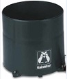
Specific details: This is a
Rainew 111
rain gauge. The link given here is representative of many sites which offer this unit.
Shop around for price, availability, and delivery times.
Rather than using the wall display counter, the switch in the gauge was wired to a
counter input on a "Five Input Network Counter".
(This is the same unit used with the Static Crash counter, which means three counter channels
are still available).
Maintenance: We will probably have to occasionally pull pine needles out of the
strainer at the bottom of the collecting funnel. Almost anything but water will probably
jam the tipping bucket mechanism.
Let's hope a bird doesn't adopt it for a nesting site.
Calibration: Not checked.
Comments:
2015 03/22
Purpose: To have a data recording channel ready to go into service.
General details: Nothing to see here folks . . . Move along . . . :-)
Calibration: No worries (yet).
Comments:
2015 03/23
Purpose: To have a data recording channel ready to go into service.
General details: Nothing to see here folks . . . Move along . . . :-)
Calibration: No worries (yet).
Comments:
2015 09/18
Purpose: To have a data recording channel ready to go into service.
General details: Nothing to see here folks . . . Move along . . . :-)
Calibration: No worries (yet).
Comments:
2015 09/18
Wind Direction
Purpose:
To measure the direction from which the
wind is coming.
Potentiometer     Cable (tower)     Cable (12-pair)   Datalogger

  High end        .                 Org/Red           "E1" - Excitation
  Common end      .                 Red/Org           "AG" - Analog Gnd

  High end        .                 Grn/Red           "2H" - Differential input
  Common end      .                 Red/Grn           "2L" - Differential input

  Wiper           .                 Blu/Red (ring)    "3H" - Differential input
  Common end      .                 Red/Blu (tip)     "3L" - Differential input
Humidity
Purpose:
To measure the amount of moisture in the air.

Barometer
Purpose:
To measure the air pressure and express it as
the equivalent "sea-level pressure".
Sensor function  Attached wire  Datalogger
  +12 Volt         Red            +12 Volt (power)
  Ground           Black          Ground   (power)
  Pressure(+)      .              "4H" Differential input
  Pressure(-)      .              "4L" Differential input
  Temperature(+)   .              "5H" Differential input
  Temperature(-)   .              "5L" Differential input
Snow depth
Purpose:
To measure the depth of the snow pack.
The sensor is an ultrasonic range-finder. In our
application it is mounted on a tower, looking straight down. It measures how
long it takes for an ultrasonic "ping" to reflect from whatever is below the
sensor. It also measures the free air temperature.
When there is no snow pack, the average measured snow depth should be
about zero ("0.0").
Wind and air temperature variations affect this sensor.
Precipitation
Purpose:
To measure the water content of all precipitation (liquid or solid)
which has fallen since the start of the "water year". This includes rain, snow,
sleet, and hail, making it an "all season" gauge. The "water year" in this area
begins on October 1st.
Note: The following is speculation, based on inspection of a SNOTEL site
and searching the web for information.
The standard
SNOTEL precipitation gauge
(which looks like a rocket motor wearing a grass skirt) is essentially a tall
12" diameter metal tube.
Assuming the annual rainfall does not over-fill the sensor, at the start of
the "water year":
If serviced mid-year, after "zeroing" the sensor, an offset amount will need
to be noted to account for the amount of fluid removed.
- Enough to provide sufficient protection at the temperatures anticipated,
even after being diluted by the anticipated amount of precipitation.
The fundamental equation for hydrostatic pressure is:
This "precipitation" data channel is borrowed from a nearby "SNOTEL" site
which is operated by the
Natural Resources Conservation Service (NRCS).
This service maintains many sites
from New Mexico to Alaska.

Static Bursts / Lightning
To get an estimate of the amount of local lightning activity.
An AM radio is tuned to an unused frequency, and listens for the static
"bursts" associated with lightning activity.
- "Fast" RC filter = 100K Ohms & 0.47 uFd -> ~ 47 millisecond time constant.
- "Slow" RC filter = 470K Ohms & 0.47 uFd -> ~220 millisecond time constant.
The outputs of the filters are buffered with output-follower op amps
Nope.
Information for this parameter will not be shown if no events have been counted
within the time period of interest (i.e. 6 or 48 hours for the "short" and "long"
weather pages). After a count is recorded the pages will keep reporting this
parameter until the time period of interest again contains no counts.
2023 05/11 - Replace "zip cord" with direct burial "Romex" to see if solid copper wire
in polyethylene insulation can survive the critters.
Rain Gauge
Information for this parameter will not be shown if no events have been counted
within the time period of interest (i.e. 6 or 48 hours for the "short" and "long"
weather pages).

Counter 3 - SPARE
Information for this parameter will not be shown if no events have been counted
within the time period of interest (i.e. 6 or 48 hours for the "short" and "long"
weather pages).
Counter 4 - SPARE
Information for this parameter will not be shown if no events have been counted
within the time period of interest (i.e. 6 or 48 hours for the "short" and "long"
weather pages).
Counter 5 -SPARE
Information for this parameter will not be shown if no events have been counted
within the time period of interest (i.e. 6 or 48 hours for the "short" and "long"
weather pages).